Loading document...
RENEWABLES
Improving Energy efficiency and carbon foot print
WIND TURBINES
15th May 2014
Incorporating Design and Access and DEED Statements Proposed installation of three 10kw Bergey Excel wind turbine on 15m mast, at Ballaman, Ballnahowe, Port Erin, IM9 6JF, For Mr John Whittaker Cheeseden Developments Ltd.
This statement is submitted in support of an application for the installation of three (3no.) Bergey Excel 10kw wind turbine with 7 metre diameter blades mounted on a mast of 15m to hub. It is proposed that the turbines are sited within a field owned by the Applicant approximately 150 metres to the south-west of the main house at the application site.
The application is accompanied by site plans, elevation and plan drawings of the proposed wind turbines. Full turbine specification, predicted noise data and photographs of the application site and its wider context are appended to this statement.
The application site comprises an area of land equating to approximately 400 sq. m comprising an area of the field of 16 sq. m that would accommodate each of the turbines the turbine and its underground concrete foundation and a cable trench also sited underground that would link back from the site of the turbine to the main electricity supply connection at the Applicant’s main house.
The location of the first turbine is towards the south west corner of the field at a grid reference of LAT 50°4′49.22″N LONG 4°46′10.93″W subsequent turbines are 21 m apart see attached drawings.
The underground cable trench would be approximately 250m in length and 300mm in width (75sq.m). The cable would generally be buried at a depth of 1 metre with the trench back-filled and the land reinstated to its existing condition. The application site currently comprises grazing land and land used for internal access within the complex of buildings belonging to the Applicant.
The application site is remote
The proposed turbines are sited are approximately 150 metres from the eastern boundary of the field where it can be accessed through gate directly from another field also owned by the client. No improvements to the existing access are considered necessary as once the turbines are in place they are virtually maintenance free.
The application is for the installation of three (3. No) free standing 10kw Bergey Excel wind turbine mounted on a freestanding 15m mast on a concrete pad foundation.
The turbine is a three bladed, horizontal axis propeller design having a blade diameter of 7 metres and a tail assembly that aligns the turbine into the wind. The length of the turbine from hub tip to tail end is 4 metres. A full technical specification and description of the Bergey Excel is attached to this statement at Appendix 2.
The blades of the turbines currently being supplied by the distributor are finished in white aircraft quality polyurethane paint with yellow leading edge tape to protect the blades from abrasion. The rotor hub and tail are also coated in yellow polyurethane paint. The distributor of the turbine has confirmed that the colour of the installation can be changed if this is considered necessary.
The mast is constructed in galvanised steel.
The concrete foundation that would be contained entirely underground with existing soil and turf reinstated over uses C35 (N/mm2) 20mm aggregate Original Portland Cement and has dimensions of 3.8m x 3.8m x 1.2m. Reinforcement is used top and bottom and in each way at 200mm centres using T12 bar.
The mass of the concrete is required to stop the overturning moment of the turbine and the reinforcement is used to stop cracking of the concrete when the concrete is in either tension or compression.
Great emphasis has been given to siting turbines to ensure minimum impact to surrounding area as a visual effect, sound and shadow flicker.
We have sited the turbines with slight reduction of efficiency in order to minimise the effect to the surrounding area.
Shadow flicker is the stroboscopic effect of light from the sun being intermittently shaded causing possible discomfort to an observer. The discomfort comes from the eyes attempting to adjust and readjust in rapid succession. Shadow flicker quickly diminishes with distance from a turbine. The affected area will lie to the east and west of a turbine up to a distance equivalent to 10 rotor diameters, that in this instance would be 70 metres from the turbine in each direction. At distances greater than 10 rotor diameters from a turbine, the potential for shadow flicker is considered to be very low.
Shadow Flicker typically occurs when:
Typically the sun rises at maximum 65 degrees north of east and sets at maximum 65 degree north of west, consequently shadow flicker only creates a potential problem if a dwelling is located within a 130 degree centred area to the east and west of a turbine.
In the case of this application there are no dwellings inside the potential shadow flicker projection area which means that shadow flicker will have no impact at any nearby dwellings.
The turbines would not unacceptably impact upon any building or feature of conservation or archaeological interest
The turbines would not unacceptably adversely affect the enjoyment and safe use of highways and the public rights of way network, especially bridleways (including during the construction phase)
| Reference Power | 10 kW at 12 m/s |
| Rotor Diameter | 7 m |
| Rotor Area | 38.5 m2 |
| Start-up Speed | 2.2 m/s |
| Cut-out Speed | None |
| Max. Design Speed | 60 m/s |
| Furling Wind Speed | 15.6 m/s |
| Warranty | 10 years |
| Annual Maintenance | None |
| Years in Production | 28 |
| Configuration | Upwind HAWT |
| Rotor | 3-blade, fixed pitch |
| Generator | Permanent Magnet, direct drive |
| Governing System | Passive, furling |
| Shutdown System | Crank out tail |
| Turbine Weight | 495 kg |
| Temperature Range | -40 to +60 Deg. C |
| Inverter(s) | 2 x Aurora 6 kW, 1-Ph 3 x Aurora 3.6 kW, 3-Ph DTI Gale 12, 1-Ph TBC |
| Blade Pitch Control | None, Fixed Pitch |
| Gearbox | None, Direct drive |
| Reference Power | 10 kW at 12 m/s |
| Rotor Diameter | 7 m |
| Rotor Area | 38.5 m2 |
| Start-up Speed | 2.2 m/s |
| Cut-out Speed | None |
| Max. Design Speed | 60 m/s |
| Furling Wind Speed | 15.6 m/s |
The 10kW EXCEL is a 7 meter diameter three-blade upwind turbine that achieves high reliability through rugged construction and a minimum of moving parts.
The rotor on the EXCEL has three pultruded fibre reinforced plastic (FRP) blades which are rigidly attached at their hubs. Pultrusion is a continuous forming process that allows for a very high glass fibre content, which results in a very high strength, yet flexible rotor blade. The basic material strength in ~100,000 psi or approximately twice the strength of low carbon steel.
Though the blades are not tapered or twisted, they nonetheless operate at ~ 80% of the maximum theoretical aerodynamic efficiency and produce very low sound levels due to the proprietary Bergey SH3035 airfoil. The SH3035 airfoil was developed using advanced computer modeling verified by wind tunnel testing by the National Renewable Energy Laboratory (NREL). The blades are protected from abrasion with a special polyurethane leading edge tape and the blades are painted with an aircraft-quality polyurethane paint after being very carefully balanced. The blades are typically painted white, but are often painted black for cold climates to promote ice-shedding.
The blades attach directly to the outside shell of the EXCEL's purpose-built direct drive 38-pole permanent magnet (PM) alternator. The alternator has an "inside-out" configuration in that the outer shell (containing the magnets) rotates about the fixed internal stator structure. Thus, the alternator incorporates the rotor hub, has no central rotating shaft, puts the front bearing in the rotor plane, and has no brushes. The output is a sinusoidal three-phase alternating current that varies in voltage and frequency with wind speed.
The turbine is aligned into the wind by a tail assembly. The tail boom and integrated rotor/alternator assembly attach to the mainframe assembly, which incorporates the yaw-axis slip-rings and the tower interface. The geometry of the mainframe creates the passive Autofurl® high wind speed protection. The mainframe offsets the rotor and yaw axes such that rotor thrust produces a furling moment about the yaw-axis. The weight and inclined pivot of the hinged tail provides a preset resistance to the rotor furling moment. Over speed control is initiated at 13-15 m/s (30-34 mph) when rotor thrust overcomes the tail resistance and restoration is caused by gravity as the wind speed subsides. The EXCEL has no shut-down wind speed. The turbine can be manually shut-down using a furling winch installed at the base of the tower.
Corrosion protection for the EXCEL is provided by hot-dip galvanizing (mainframe, tower adapter, and tail boom), electro-zinc plating, and polyurethane paint systems. FRP components, such as the blades, are protected by ultraviolet-inhibiting resin additives and sub-surface "scrim cloth" UV barrier. The blades have polyurethane leading edge tape for protection against erosion.
The EXCEL has only four moving parts, no adjustable elements, and no grease fittings. No scheduled maintenance is required beyond biannual inspections and replacement of the outer three feet of blade leading edge tape every 4-10 years. From the assessment of the turbines that have been operational for 30 years, Bergey can declare a design life of 50 years.
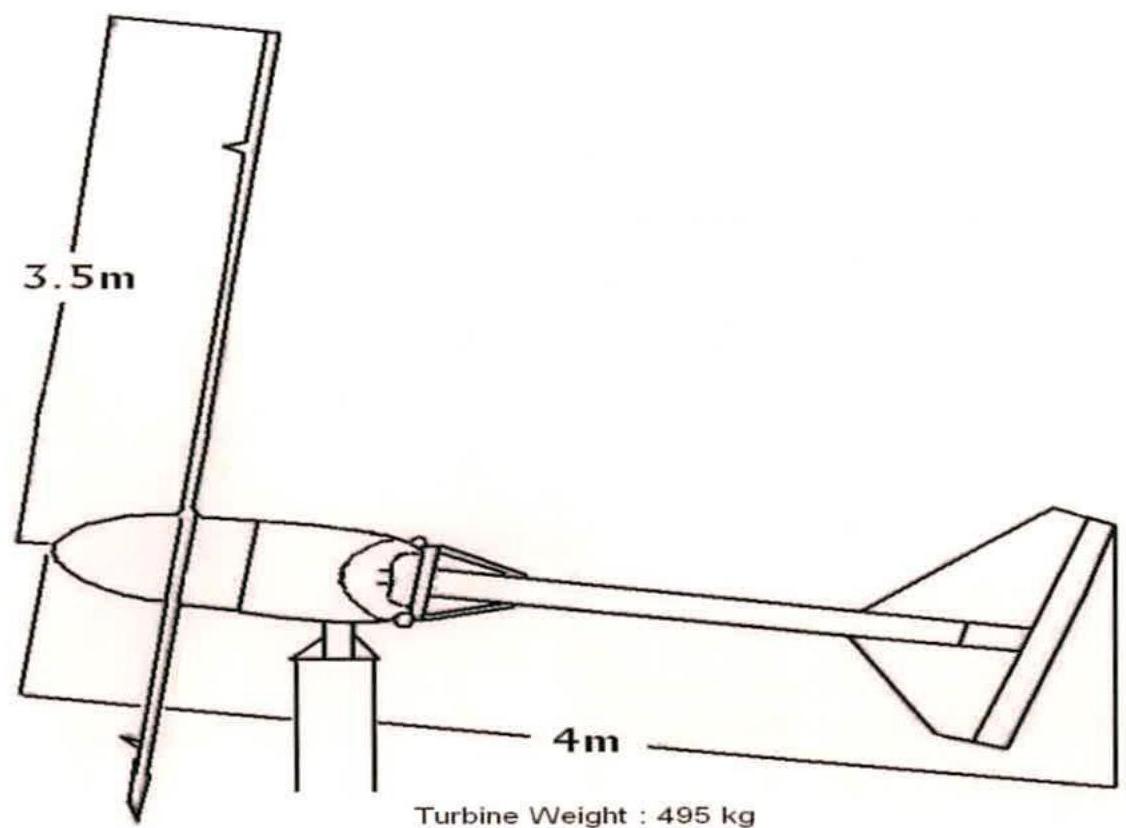
Turbine Weight: 495 kg
Copyright in submitted documents remains with their authors. Request removal