Loading document...
Contact: Kevin Gregory Telephone: 01634 290999 E-mail: [email protected] Project reference: E9860 Date of Initial issue: 4th November 2019 Revision: Initial
Planning Consent Information Mechanical Ventilation & Environmental Control Equipment KFC UKI KFC Restaurant Peel Rd Douglas Isle of Man IM1 5ED
EXTERNAL PLANT NOISE CRITERIA
This specification covers standards for the selection, supply, delivery, installation, testing and commissioning of Kitchen ventilation in accordance with HVCA Specification DW/172 for Restaurant developments. The cooking of food involves appliances releasing heat, steam, fumes and airborne grease.
The cooking process requires extract ventilation for the removal of fumes, smoke and vapours generated by the cooking activity.
To provide an acceptable working environment for all kitchen staff by the extraction / removal of heated air, fumes, steam and cooking smells, as well as preventing condensation. The extract canopies are designed to enable ease of access for cleaning throughout the system and distribution ductwork and primary fan equipment.
All fumes and odours from the food preparation areas of the kitchens shall be mechanically extracted utilizing an extract canopy specifically designed and installed by a nominated specialist to remove all cooking odours. This will take into account the dimensions of the kitchens in question, the type of grease filters used in the application and the cooking equipment within the grouped cooking range.
All fan equipment, ductwork and filter housing shall be so mounted and installed so as not to give rise to a noise nuisance. Any noise generated by the extraction or supply systems as a whole shall not exceed the pre-existing hourly background noise level at nearby residential accommodation by more than 5dB(A). When measured and rated in accordance with BS 4142, entitled Method of Rating Industrial Noise Affecting Mixed Residential and Industrial Areas 1997
The canopies will be sited over the grouped cooking equipment, or any heat, steam or grease producing equipment.
The canopies shall overhang the grouped cooking range by not less than 250mm and will be mounted at a height no lower than 2000mm from the finished floor level to the underside of the canopy.
Where specifically required or instructed, an automatic fire suppression system will be installed to protect the cooking appliances, extract canopies and associated distribution ductwork. Fire suppression systems will be of the “Ventam, K-Nobel or Ansul” type, tested and approved to UL 300 specification with automatic and manual activation. Fire suppression systems will be designed, installed and commissioned by LPC1204 approved installers.
The extract canopies shall be constructed from 18 swg (1.22mm thick) stainless steel type 304. All visible surfaces shall be ultra fine grain satin polished to 280 grit, and Polythene protected during installation. All constituent parts must be suitable for use in a working kitchen environment.
The canopies shall be cut, punched and folded into sub sections of up to 6000mm in length and factory assembled by means of computer controlled seam welds, and non visible mechanical fixings. All joints shall be formed to enable ease of cleaning with no cut edges or corners, which shall become an encumbrance to cleaning requirements. All metal edges shall be rolled smooth and shall be free from any sharp edges or projections.
The canopy lower edge at each end and the rear shall be formed into a condensation channel with inclined internal elevation to simplify cleaning requirements, the inner edges having crush folded safety finish.
When constructed, the canopies should be flush with sealing surface as should any ducting within the kitchen itself. This is to prevent the creation of a shelf which would permit the collection of
dust etc. where this is not possible infill panels are to be fitted so there are no dust traps. All infill panel requirements shall be constructed from the same material as the canopy.
Stainless steel sheets of the same grade and polish finish should be fitted to the rear and side walls below the canopy. This should be, as a minimum, the width of the canopy and should be flush with the base of the canopy, the wall and down to the floor. All joints between the splashback, cooking equipment and the canopy should be sealed with a silicone sealant. Silicone sealant should be applied only when absolutely necessary to joints in a neat finish not protruding the metal surface. Silicone joints will not be accepted as an alternative for a welded or poor constructed joint.
The canopies shall be fitted with vapour proof lamps suitable for use in damp atmospheres. The lamps should have a diffuser, which can also withstand high temperature. Recess lighting is preferred to bulkhead fittings. Lighting within the canopies shall provide a minimum of 500 lux at the working surface.
All fans are to adequately sized to overcome the system resistance and to provide the required extraction/supply rate specified. Multiple fans rather than single units should be used to reduce noise in instances when the system resistance is inherently high.
All fan motors are to be totally enclosed, air cooled, class F rated, with motor protection IP55. All single phased motors are to have “sealed for life” bearings. The fan motor should have an operating temperature of -40 deg. Cent. to +50 deg. Cent.
All fans will be provided with suitably rated on/off variable speed controllers, and all fan equipment having local isolators and emergency stops fitted adjacent to the applicable equipment. Fans should be fitted with necessary resilient mounting to prevent noise and vibration transfer to the kitchen, other unit rooms and the external environment.
The Contractor will ensure that the fans are capable of producing the required air volumes as specified. All fans and motors arrangements shall be capable of running at 10% over the maximum specified duty.
The Contractor shall ensure that fan motors are suitable for the electrical supply available to the building.
Casing mounted fans shall have internal vibration isolation. Duct mounted fans shall have flexible duct connections consisting of or be externally protected by material having a fire penetration time of at least 15 minutes when tested in accordance with BS 476 Part 8 and shall comply with BS 476 Part 7, Section 2, Clause 2.8 (Class 1 : surface of a very low flame spread properties).
Fans shall be selected to meet the specified noise criteria.
The construction of the fan shall be such that is capable of withstanding the pressures and stresses experienced under continuous operation.
Fan casings shall be constructed such that access can easily be gained to motors and impellers, and that these can be removed if required for maintenance or replacement.
The canopies should be fitted with internal extract plenum(s) with grease filters cells across its length. The filters should be of a sufficient size and number to ensure that the velocity through them does not lead to grease “carry over” into the ductwork and onto the extract fan.
The grease filters should have rigid frames in stainless steel baffle filters of sufficient density to capture and hold airborne grease. Filters shall fit correctly into holding frames to eliminate any extracted air passing around the filter.
The extracted fumes shall first be passed through these filters designed to remove the grease entrained in the fumes; the filters shall be removed and cleaned of their deposits at the end of each working day.
The grease filters should be easily removed and should be adequately sized to fit easily within dishwashers to facilitate easy cleaning.
The location of the filters should be such that it is not affected by the heat of wall mounted equipment, such as grills. This is particularly important with replaceable filter fittings, which carbonize at high temperature.
Kitchen canopy exhaust ductwork shall be constructed and installed in accordance with HVCA Specification DW/172 and HVCA Specification DW/144. Ductwork shall be routed to external source in the shortest possible route, without excessive use of bends and horizontal ductwork installation.
Ductwork shall be suitable for kitchen extract systems, with smooth internal surfaces that facilitate easy removal of grease deposits.
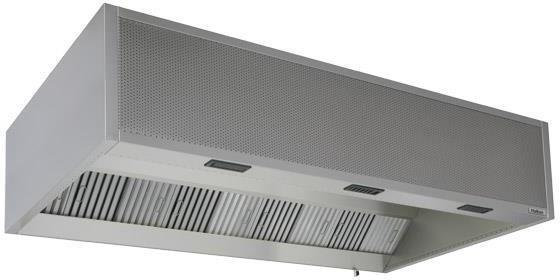
The kitchen area shall have a mechanical forced air system, with a side-wall mounted canopy arrangement over the main grouped cooking equipment, and supply air system with spot coolers fitted to the underside of the canopy for the cooking operatives benefit. The extract system shall have an on/off speed controller sited away from the kitchen area to suit site and operatives requirements. The canopy shall be a “Capture Jet” type canopy with 10% of the overall extract air from the canopy, supplied through an insulated plenum fitted integrally to the canopy.
The supply air shall then be discharged through personal spot ventilators, with each spot coolers having internal volume control. The supply air to the canopy shall be from the primary packaged unit, with the remaining supply air to the kitchen also supplied by the packaged roof top unit. The supply directly to the canopy shall constitute 45% (85% room total) of the extract air volume to achieve a negative pressure within the kitchen area. The canopy shall be sited over the grouped cooking range of equipment as per tender drawings.
The canopy arrangement shall be as follows:
5800mm Long x 1500mm Wide x 555mm High. (Dimensions to be checked prior to site start) Four-sided outer valance casing.
The canopy lower edge at each end shall be formed into a condensation channel with inclined internal elevation to simplify cleaning requirements. Full area horizontal ceiling plate, manufactured in tray form, fixed and sealed into the outer valance casing.
Full length single sided extract plenum, fixed and sealed to the canopy outer structure and complete with: -
1 No. full length insulated integral make-up air plenum to introduce make-up air into the canopy and into the kitchen area, comprising:-
LED recessed luminaries manufactured to IP65, steam heat and grease proof to give an average level of illumination of 500 Lux upon the working surfaces.
Grease collection tray’s
DUTIES: Canopy Extract volume 2.20 m3/sec. at a constant pressure drop of 140 pascals Canopy Supply volume 0.945 m3/sec. at a constant pressure drop of pascals.
All duties to be checked against the manufacturers filter performance data.
The chip fryer in the kitchen area shall have a mechanically forced air system from an integral supply fan within the front of the hood. The extract system shall have an on/off speed controller sited away from the kitchen area to suit site and operatives’ requirements. The canopy shall be a “Capture Jet” type canopy with extract connections only to hood.
DUTIES: Canopy Extract volume 0.51 m3/sec. at a constant pressure drop of 85 pascals All duties to be checked against the manufacturers filter performance data. NOTE: 85% of the air extracted from the kitchen shall be supplemented by supply air.
TYPICAL KFC CANOPY DESIGN
NOTE: Items detailed within this section are external plant items only.
KFC’s have a common philosophy to provide a comfortable environment within restaurants for customers, with all areas having thermostatic control and adequate ventilation, which is further extended to their staff.
This section covers the technical information with respect to external plant equipment.
The Trade Restaurant area shall be provided with its cooling, heating and ventilation requirements via a mechanically forced air movement system, derived from a VRF refrigerant heat recovery air conditioning system. The indoor units mated to this system are above ceiling ducted units operating on a vapour comprehension cycle, utilising refrigerant R410A.
The units shall operate on a re-circulated basis, with the minimum fresh air requirement in conjunction with the specified occupancy level in accordance with Document F1 of Building Regulations, set and locked on the fresh air intake opposed blade volume control damper. The specific fresh air requirement shall be in accordance with Building Regulations and CIBSE Guide relating to minimum fresh air requirements per individual occupant. The actual quantity of fresh air is indicted within this specification and associated tender drawing.
Supply and return air distribution shall be through fabricated galvanised steel ductwork, routed generally as per the tender drawings, with air terminal devices situated within the false ceiling structure, dissipating air in the specified patterns.
Temperature control of the area shall be sensed at room conditions with a high-level room mounted zone temperature sensor, and the mechanical refrigeration plant controlled accordingly.
The heat rejection plant in the rear yard shall be fully weather proofed, treated and situated on raised condenser blocks between unit and base, with levelling shims fitted were necessary. Allowances shall be made during the installation of the external condensing units to limit vibration.
The unit base shall be secured to the concrete floor finish using proprietary masonry anchor fixings.
The contractor shall be responsible for ensuring that the indoor and outdoor primary plant has the specified access space for maintenance and service around the packaged unit in accordance with the manufacturer’s recommendations.
Restaurant,
4 of Mitsubishi PLFY-P50VEM-E Cassette Type Units 840 x 840 x 258 High
24KG 26-27-29-31 DBA
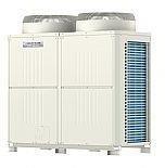
Door Curtain 1 of VRF HP1000 DXE AC 1300 x 306 x 468 High 46KG 50-55-58 DBA CU1 Mitsubishi R2 series PURY550 YNW-A External condenser Heat recovery outdoor unit 1750 X 740 X 1858 High 337KG 70DBA This unit is a common unit serving all internal air conditioning plant, regardless of designated separate internal areas. I.E. One condenser serves all areas.
The Kitchen and staff areas shall be provided with its cooling, heating and ventilation requirements via a mechanically forced air movement system, derived from a VRF refrigerant heat recovery air conditioning system. The indoor units mated to this system are above ceiling ducted units operating on a vapour comprehension cycle, utilising refrigerant R410A.
The units shall operate on a re-circulated basis, with the minimum fresh air requirement in conjunction with the specified occupancy level in accordance with Document F1 of Building Regulations, set and locked on the fresh air intake opposed blade volume control damper. The specific fresh air requirement shall be in accordance with Building Regulations and CIBSE Guide relating to minimum fresh air requirements per individual occupant. The actual quantity of fresh air is indicted within this specification and associated tender drawing.
Supply and return air distribution shall be through fabricated galvanised steel ductwork, routed generally as per the tender drawings, with air terminal devices situated within the false ceiling structure, dissipating air in the specified patterns.
Temperature control of the area shall be sensed at room conditions with a high level room mounted zone temperature sensor, and the mechanical refrigeration plant controlled accordingly.
The heat rejection plant in the rear yard shall be fully weather proofed, treated and situated on raised condenser blocks between unit and base, with levelling shims fitted were necessary. Allowances shall be made during the installation of the external condensing units to limit vibration.
The unit base shall be secured to the concrete floor finish using proprietary masonry anchor fixings.
The contractor shall be responsible for ensuring that the indoor and outdoor primary plant has the specified access space for maintenance and service around the packaged unit in accordance with the manufacturer’s recommendations.
The unit serving the Trade Kitchen including Staff Room/Managers Office & Dry Goods area shall be as follows: -
2 of Mitsubishi PEFY-P100VMA-E2 ducted internal void unit 1400 x 732 x 250 High 26KG 25-29-32 DBA
Mitsubishi PEFY-P20VMA-E2 ducted internal void unit 700 x 732 x 250 High 22KG 23-25-26 DBA
CU1
Mitsubishi R2 series PURY550 YNW-A External condenser Heat recovery outdoor unit 1750 X 740 X 1858 High 337KG 70DBA This unit is a common unit serving all internal air conditioning plant, regardless of designated separate internal areas. I.E. One condenser serves all areas.
The main extract system within the kitchen shall serve the single wall mounted canopy arrangements as described in earlier sections of this document. The main extract fan shall also serve both the Main Canopy and Chip Fryer Canopy. The fan is mounted externally in the rear yard area.
The extract fan equipment shall be as follows: -
EF1
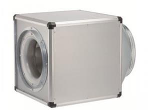
Helios Giga Box Fans Limited
Model GBD 560/4/4 T120 EC Motor: 2800 watts 4 pole1400rpm Air Flow: 13370 ³M / S Sound Level: 49dBA@4 metres Electrical: 400 volt / 3 phase / 50 Hz Weight : 83kg Dimensions: 800mm Width x 800mm Depth x 800 Height

The main supply air system within the kitchen serves the single wall mounted canopy arrangements as described in earlier sections of this document. The supply fan shall also serve both the Main Canopy and general areas via ceiling mounted diffusers. The fan is mounted internally within the kitchen ceiling void. Details are included in this document for reference even though the equipment is not located externally
The supply fan equipment shall be as follows: SF1
Helios Giga Box Fans Limited
Model GBD EC500B Motor: 2800 watts 4 pole1400rpm Air Flow: 10,500 ³M / S Sound Level: 46dBA@4 metres Electrical : 400 volt / 3 phase / 50 Hz Weight : 83kg Dimensions: 800mm Width x 800mm Depth x 800 Height

The general extract fan serves the toilet and staff area toilets and general areas. The fan is mounted internally within the staff area ceiling void. Details are included in this document for reference even though the equipment is not located externally
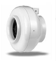
The extract fan equipment shall be as follows: EF2 Elta Inline Fans Limited
Model SJ250A in line centrifugal tube fan. Motor: 180 watts 2 pole 2450rpm Duty: 0.24 cu.m/sec @ 100 pascals Sound Level : 53dBA@3 metres Controller : WC lighting circuit Electrical : 230 volt / 1 phase / 50 Hz Weight : 5.5kg Dimensions: 335mm overall diameter x 230mm long
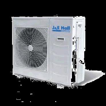
There are three cold rooms serving the KFC unit. The heat rejection condensers serving the cold rooms are mounted in the rear yard at a height below the yard wall, and one separate condenser serves each cold room unit.
Chiller Room: Split Refrigeration System
Model - Fusion Range
Freezer Room: Split Refrigeration System
Prefix - Freezer Room
Model - Fusion Range
Veg Chiller Room: Split Refrigeration System
Model - Fusion Range
Condenser Model - JEHR-0100-B1-M-1 Dimensions - 876 (W) x 420 (D) x 607mm (H) Weight - 55 Kgs Electrical Supply - 230-1-50 Hz Main Fuse Rating - 20amps Net noise level - 28dBa
Copyright in submitted documents remains with their authors. Request removal