Loading document...
A condition of the original Registered Building Consent approval required a method statement to be submitted to demonstrate the means employed and sequencing of the works to create the new openings in the South Transept gable and the new kitchen door.
The following provides details of recent structural stabilising of the gable wall, ongoing monitoring and the sequencing of the work as proposed by John Gray Structural Engineer. To be read in conjunction with their structural drawings:-
The South Transept wall has been subject to regular monitoring over recent years due to detected movement of external sections of the solid masonry.
The results of the monitoring have been reviewed by the Structural Engineer, John Gray, who recommended remedial works to stabilise the west wall of the South Transept. This was undertaken in 2021 by Peter Cox Ltd who installed Cintec anchors in the stonewall to the engineer's design.
Additional stabilising work to install stainless steel anchor pins to the south gable to tie the masonry together was undertaken to the south gable in January 2023 by CoreFix Ltd, again to the specification of the Structural Engineer and as per the attached sketch.
Monitoring prism are attached to the west and south walls of the transept and are surveyed by WGS Limited.
Measurements of the south gable were taken in August 2022 and at the beginning of February 2023 following completion of the installation of the stainless steel pins. A further survey on 4th August indicated that no further significant movement has occurred in the wall. John Gray has reviewed the information and is satisfied that the wall is stable and that works to form the new opening below the south transept window can commence.
A further monitoring survey of the south gable is due to be undertaken on 31st August to provide an additional check prior to forming the opening.
John Gray has provided a sequenced method by which new openings are formed through the existing masonry walls. The proposed method minimises the any risk of damage to the structure and provides sufficient support to the retained structure while the openings are being formed. John Gray has reviewed the proposal and is confident that the method is appropriate for the Cathedral. He will also monitor the structural work as it progresses to ensure that the sequencing follows his specification.
The following specifies the sequence of forming the opening as set out on the Structural Engineers drawing 7864/01:-
Provide and construct a suitable dust proof booth for the whole of the works within the Cathedral and weather proofed security entrance and access to the outside face.
Break out and form the new 2550 mm wide door opening in 3 sections through the 900 mm thick rubble masonry wall as shown on the section elevation. The 3 sections to consist of the following sequence:
Install galvanised steel universal column sections S355 steel beams in sections (9 units in total), complete with bolted end plates and 150 mm minimum end bearings.
Sequentially install thick galvanised mild steel plates and packing the void between the steel beams and stonework over with 1:3 semi dry mortar packing, fully rammed.
Leave gaps to the beams connections: plastic wedges to be driven between the masonry and beam above and deflect the beams by 5 mm ; fully pack these positions with 1:3 semi dry motor.
Form door opening reveals with concrete blockwork in cement lime mortar (1:1:3); blockwork to each reveal to be restrained with 2no. 10mm diameter stainless steel threaded rods with epoxy resin anchors at 450 vertical centres, with minimum 300 mm embedment to rubble filled core; filling joint between blockwork and stonework; as detail 1
The following specifies the sequence of forming the opening as set out on the Structural Engineers drawings 7864 / 30 to 33:-
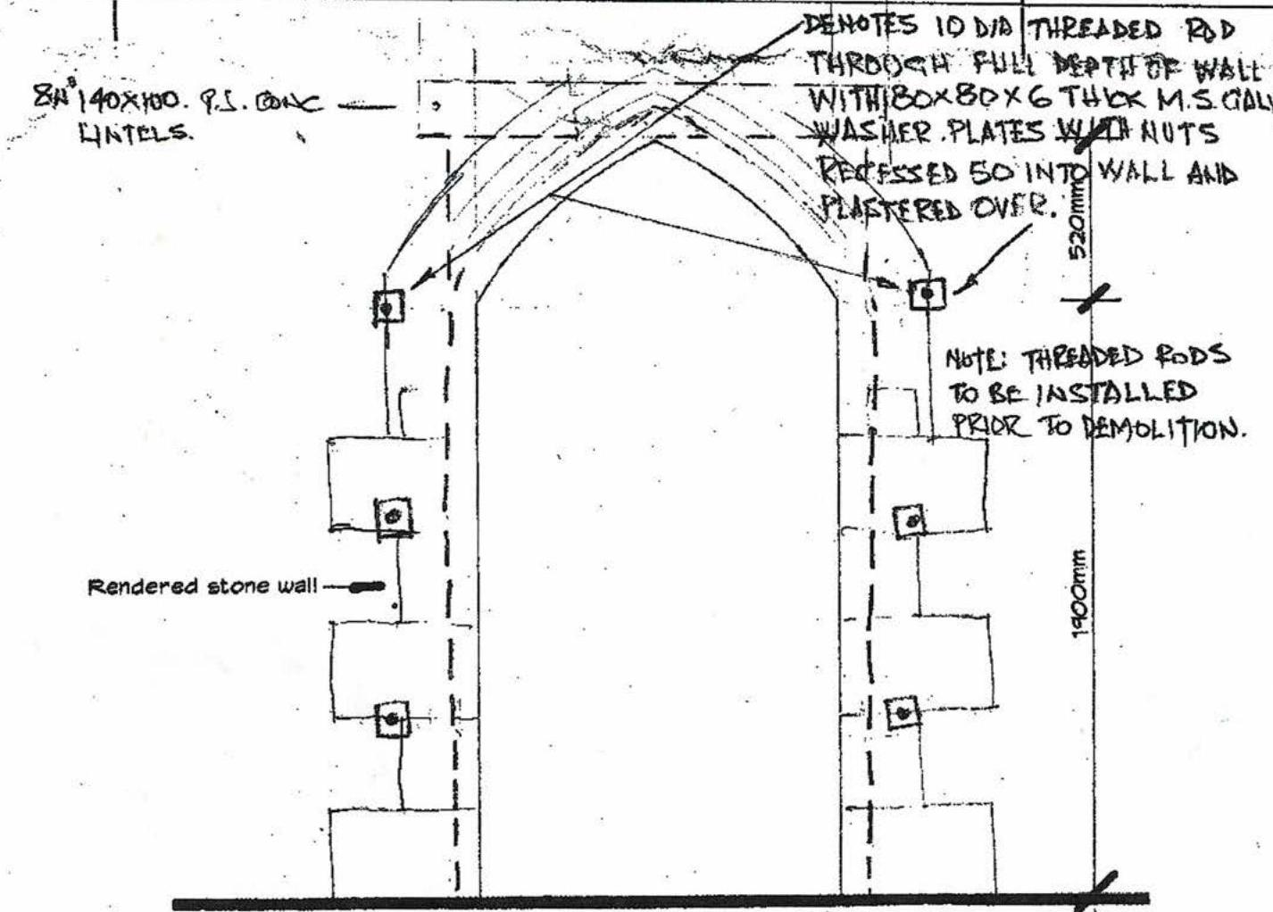
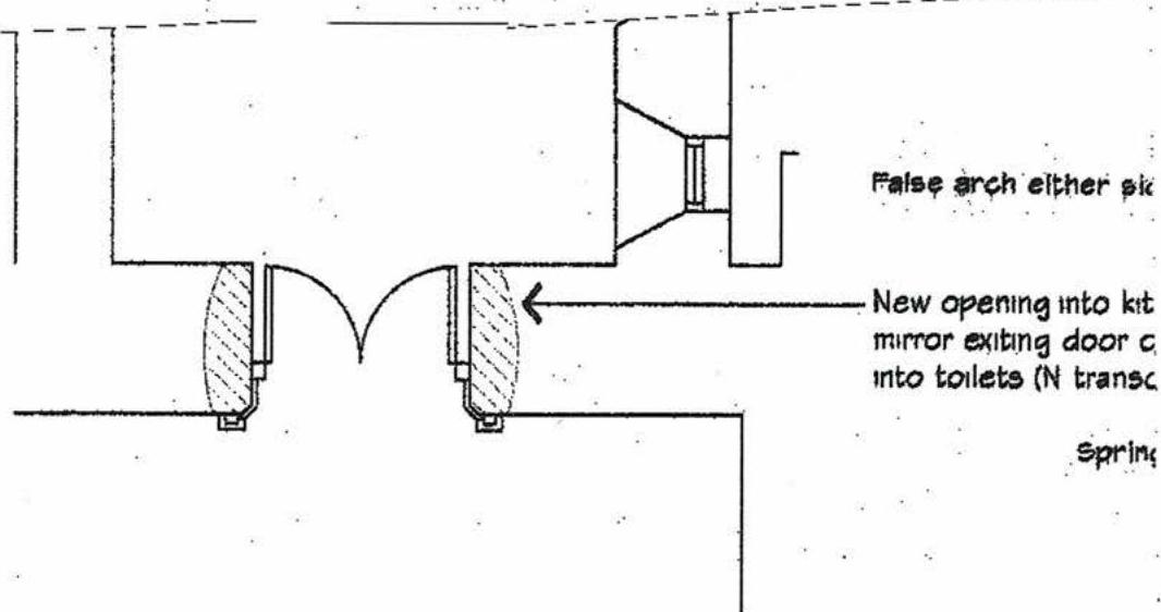
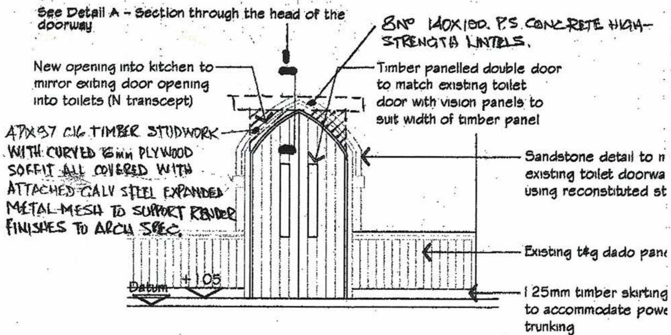
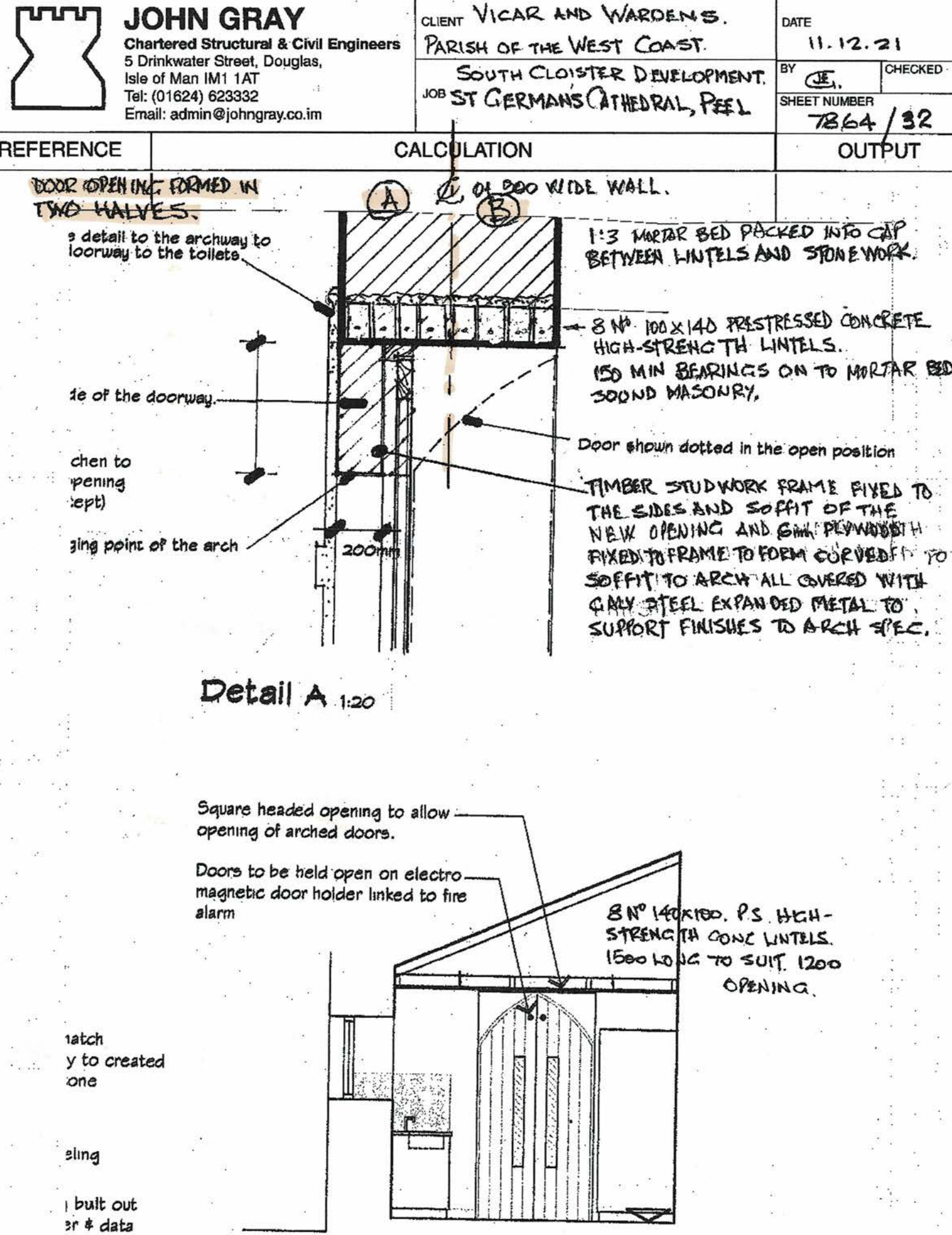
Form the opening to the kitchen in accordance with the Structural Engineers sequence of works, formed in two halves as per Detail A on Drwg 7864/32; include for cutting out and inserting 8no. long prestressed lintels; lintels to be fully bedded and packed with cement mortar (1:3); between the top of the lintels and the stonework.
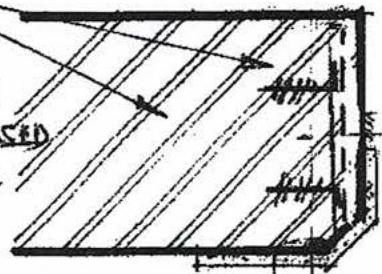
Install 6no. 10mm diameter threaded rods drilled through the full thickness of the 900 mm thick stone wall as shown on Drwg no 7864/30; include for thick mild steel galvanised washer plates with nuts to each side; allow for recessing the end plates 50 mm into the thickness of the wall.
Sequencing: The door opening is to be formed in two halves ( ) as indicated as the attached drawings, so that the first section of wall is supported by pre-stressed concrete lintels before moving on to the next section.
Following demolition of the door opening stonework, allow for trimming the reveals of the opening and drilling and installing 2no. 250 long M8 galvanised threaded rods (L shaped 200 with 50 long leg); rods drilled and installed at 400 vertical spacings to each opening reveal (approx 28no. Rods); threaded rods to be resin anchored to the stonework.
Apply two coats 20 thick pigmented lime render to the reveals; reveals to have chamfered arrises as indicated and set out in quoin detail to the front elevation and gothic arched head; allow for all the formwork to form the detailing; allow for additional dubbing out to line and level prior to installing basecoat render. Render to reveals to have galvanised steel expanded metal mesh between the two coats of lime render; allow for tying the mesh securely to the threaded rods.
Chartered Structural & Civil Engineers 5 Drinkwater Street, Douglas, Isle of Man 1M1 1AT Tel: (01824) 623332 Email: [email protected]
Client Vicar & Wardens Parish of the West Coast DATE 23-11-22
SJ EY JEG CHECKED SH EY GJSSEN 7864/Sk01
Outlines traced from drawing 15MS004 prepared by WGS Ltd dated July 2022 This drwg to be read in conjunction with 7864/Sk02
Anchorage Point Locations – See schedule on sheet 7864/Sk02
Treatment of gap and restraint between masonry window head and surrounding masonry determined at later date following closer inspection.
Denotes outline of external structure Denotes outline of internal structure Denotes anchorage points Denotes anchorage points W11 W12 E12 E11 E11
W9 W8 E8 E9
W6 W7 E6 E7
Denotes existing Cintec anchors
W4 E5 E4 E3
W3 W2 E1
W11 E8
Top of plinth
REMEDIAL WORKS Structural Engineer's drawing showing the location of the anchor pins to the South Transept gable wall. The work was completed by CoreFix in January 2023.
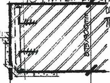
BENOTES 10 DIA THREADED ROD THROUGH FULL DEPTH OF WALL WITH BOX 80 X 6 THICK M.S. ONLY WASHER PLATES WITH NUTS PROCESSED 50 INTO WALL AND PLATTERED OVER.
NOTE: THREADED RODS TO BE INSTALLED PRIOR TO DEMOLITION.
DENOTES MB GALY THREADED 1. SHAPED ROD SET IN EPOXY MORTAR AT 400 VERTICAL SPACING. MESH TIED TO RODS.
(ROD LENGTH MAY REQUIRE TO BE INCREASED TO SUIT SITE CONDITIONS)
Plan 1:20
1180mm FINISHED OPENING.
GALY STEEL EXPANDED METAL MESH SANDWICHED BETWEEN TWO 20 THICK LAYERS OF TWO COAT LIME RENDER FINISHED WITH PIGMENTED SPECIALIST RENDER TO PROVIDE STONE EFFECT TO MATCH DISTINCTION.
OPENING TO ARCH SPEC.
REMOVAL OF STONE CARRIED OUT IN TWO PHASES TO FORM OPENING.
New internal door opening South Transept - Cathedral Isle of Man
Proposed Plan 1:50
Chartered Structural & Civil Engineers 5 Drinkwater Street, Douglas, Isle of Man IM1 1AT Tel: (01624) 623332 Email: [email protected]
COURT VICAR AND WARDENS. PARISH OF THE WEST COAST. SOUTH CLOISTER DEVELOPMENT. JOB ST GERMANS (ATHEORAL, PEEL) CALCULATION DATE: 11.12.21
BY GE.
CHECKED
SHEET NUMBER: 7864/92
OUTPUT
DOOR OPENING REMED IN TWO HALVES.
Detail A 1:20 Square headed opening to allow opening of arched doors. Doors to be held open on electro-magnetic door holder linked to fire alarm. BIN 140 (KIDD, PS. HCH-STRENGTH CONF. LINELLS. 1500 LOUC TO SUIT, 1200 OPENING.
| CLIENT | VICAR & WARDENS PARISH OF THE WEST COAST | DATE | 17.6.21. |
|---|---|---|---|
| JOB | DOOR OPENING. KITCHEN/SOUTH TRANSEPT | BY | ☑ CHECKED |
| SHEET NUMBER | 7864/33 |
| REFERENCE | CALCULATION | OUTPUT |
|---|---|---|
| ☑ ☑ ☑ | WALL APPROX 300 THICK STONEWORK IN LIME MORTAR. REMOVE STONEWORK IN TWO HALVES, (A) AND (B) * 350 WIDE GALV EXPANDED METAL MESH FIXED TO SURFACE OF 2ND LIME SAND RENDER COATS APPLIED TO STONEWORK WHEN HOLLOWS AND POCKETS HAVE BEEN FILLED WITH LIME MORTAR. CENTROL SECTION OF MESH TO BE FIXED FOLLOWING COMPLETION OF STAGES (A) AND (B). 10 DIA THREADED GALV ROD WITH BOX 80 X 6 GALV WASHER PLATES WITH NUTS RECESSED INTO WALL AND PLASTERED OVER. * MB GALV THREADED ROD 150 SET IN EPOXY MORTAR AT 400 VERTICAL CENTRES, MESH TIED TO RODS TYPICAL PLAN ON JAMB TO DOOR OPENING TO KITCHEN. |
Copyright in submitted documents remains with their authors. Request removal